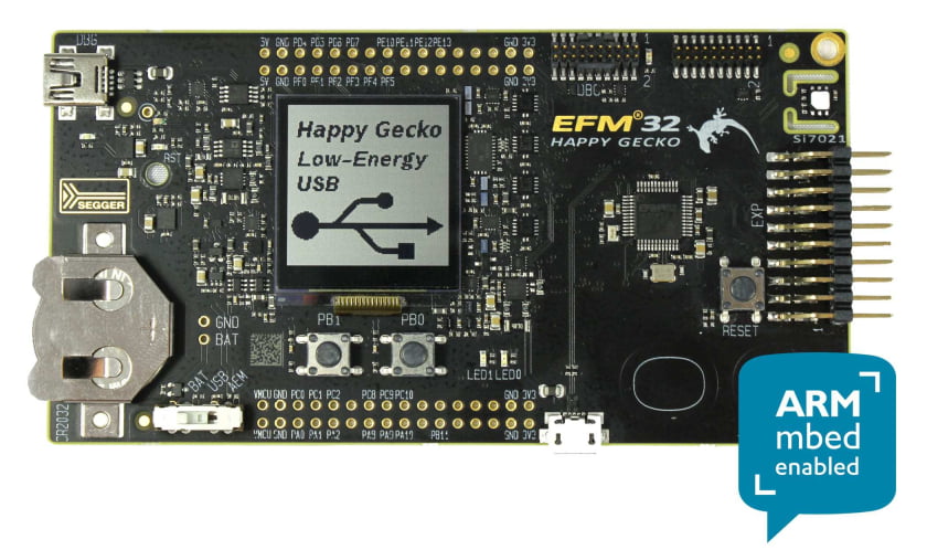
Hello people! I’ll show you how to use timers for event generation.
Let’s say we want to use one of the chip timers to toggle one of the pins.
/*
 1. Divide source clock by 1:
    writes 0 in 25-th bit of the register (counting of the bits starts from the 0)
*/
 TIMER0->CTRL |= TIMER_CTRL_PRESC_DIV1;
 /*
 2. Connect timer to clock source
     writes 0 in 16 to 17-th bits of the register (counting of the bits starts from the 0)

Additional possibilities are:
    a) Get the clock from the CC1 (Compare/Capture Channel 1 Input) pin
    b) Get the clock from the underflow(down-count) or overflow(up-count) in the lower
 numbered neighbor Timer (in our case, we cannot use this option, I think)

*/
 TIMER0->CTRL |= TIMER_CTRL_CLKSEL_PRESCHFPERCLK;
 /*
 3. Check the timer mode
    a) 0 – Up-count mode
    b) 1 – Down-count mode
    c) 2 – Up/down-count mode
    d) 3 – Quadrature decoder mode

    In our example we’ll take option a)
 */
 TIMER0->CTRL |= TIMER_CTRL_MODE_UP;
 /*
 4. We will enable interrupt on timer overflow (because we choose counting up, in case of counting down, we’ll need to set a bit for the underflow interrupt )
 */
 TIMER0->IEN |= TIMER_IEN_OF;
 /*
 5. Clear all interrupt flags
 Equal to TIMER0->IFC = 0x773
 */

TIMER0->IFC |= TIMER_IFC_CC0 | TIMER_IFC_CC1 | TIMER_IFC_CC2 | \
     TIMER_IFC_ICBOF0 | TIMER_IFC_ICBOF1 | TIMER_IFC_ICBOF2 | \
     TIMER_IFC_OF | TIMER_IFC_UF;

/*
 6.  Lets define the value to count up to it (otherwise the counter will count up to 0xFFFF)
 We ensure the length of the value, by setting the value to the TOPBuffer register and not to TOP register itself
 The value passed to the TOP register in the next tick of the MCU
 If you want to change the value during run time, I thing it would be better to use the TOP register directly
 */
 TIMER0->TOPB = 0xA; //up to 10
 /*
 7. Start the timer
 */
 TIMER0->CMD = TIMER_CMD_START;
You should remember, that before these steps, you need to enable NVIC interrupts for timer like this:
NVIC_EnableIRQ(TIMER0_IRQn);And, of course, enable the timer clock:
CMU_ClockEnable(cmuClock_TIMER0, true);To handle the enabled interrupts we need to define the interrupt handler:
void TIMER0_IRQHandler() {
 /*
 If it’s a required interrupt, that we are waiting for
 */
     if(TIMER0->IF & TIMER_IF_OF) {
         //clear the interrupt flag
         TIMER0->IFC |= TIMER_IFC_OF;
        /*
         Toggle the pin number 0, in port D
         We set 1, in DOUTTGL register, in place of required pin
        */
         GPIO->P[gpioPortD].DOUTTGL = 1 << 0;
     } //end of if
 } //end of handler